-40%
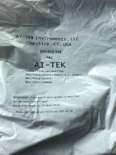
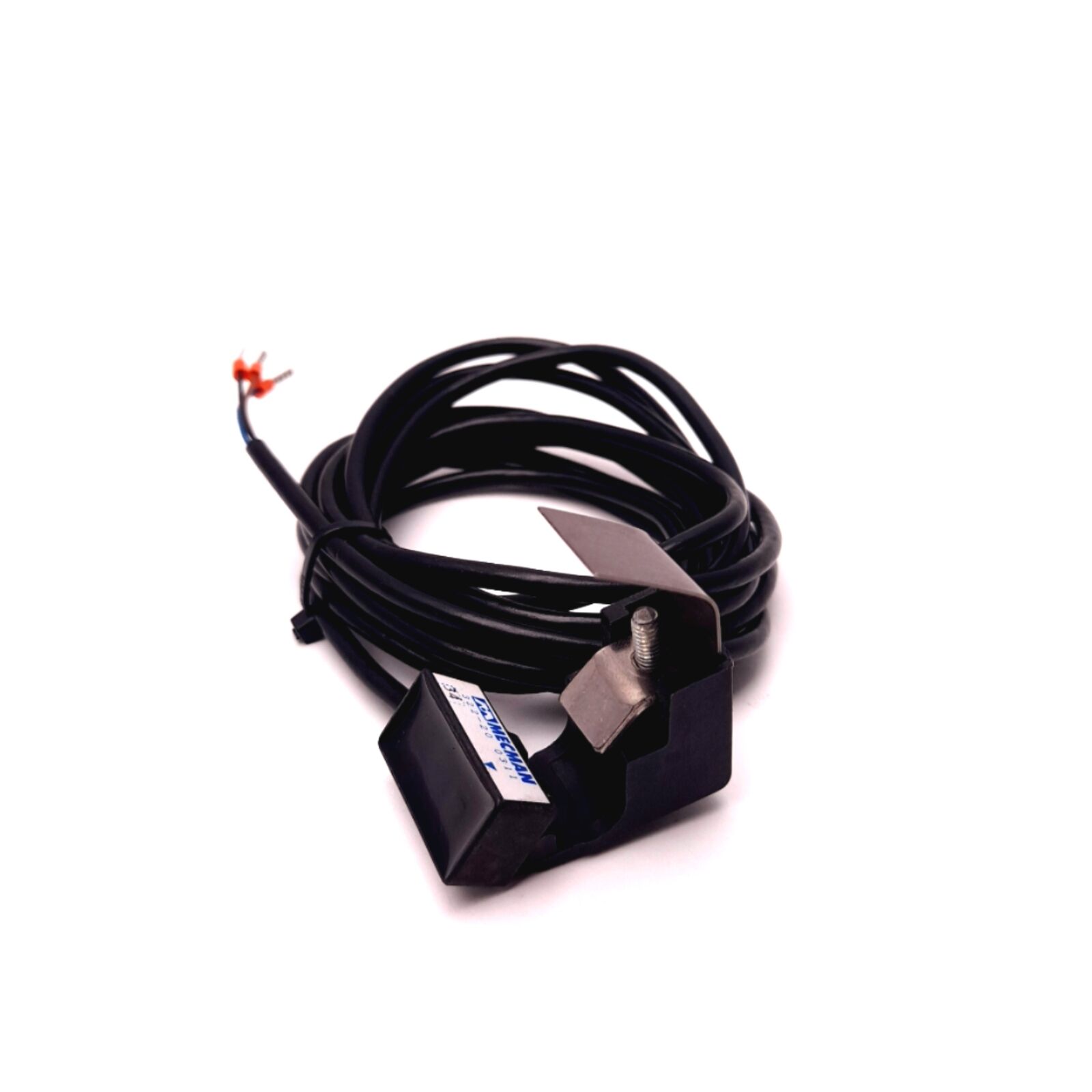
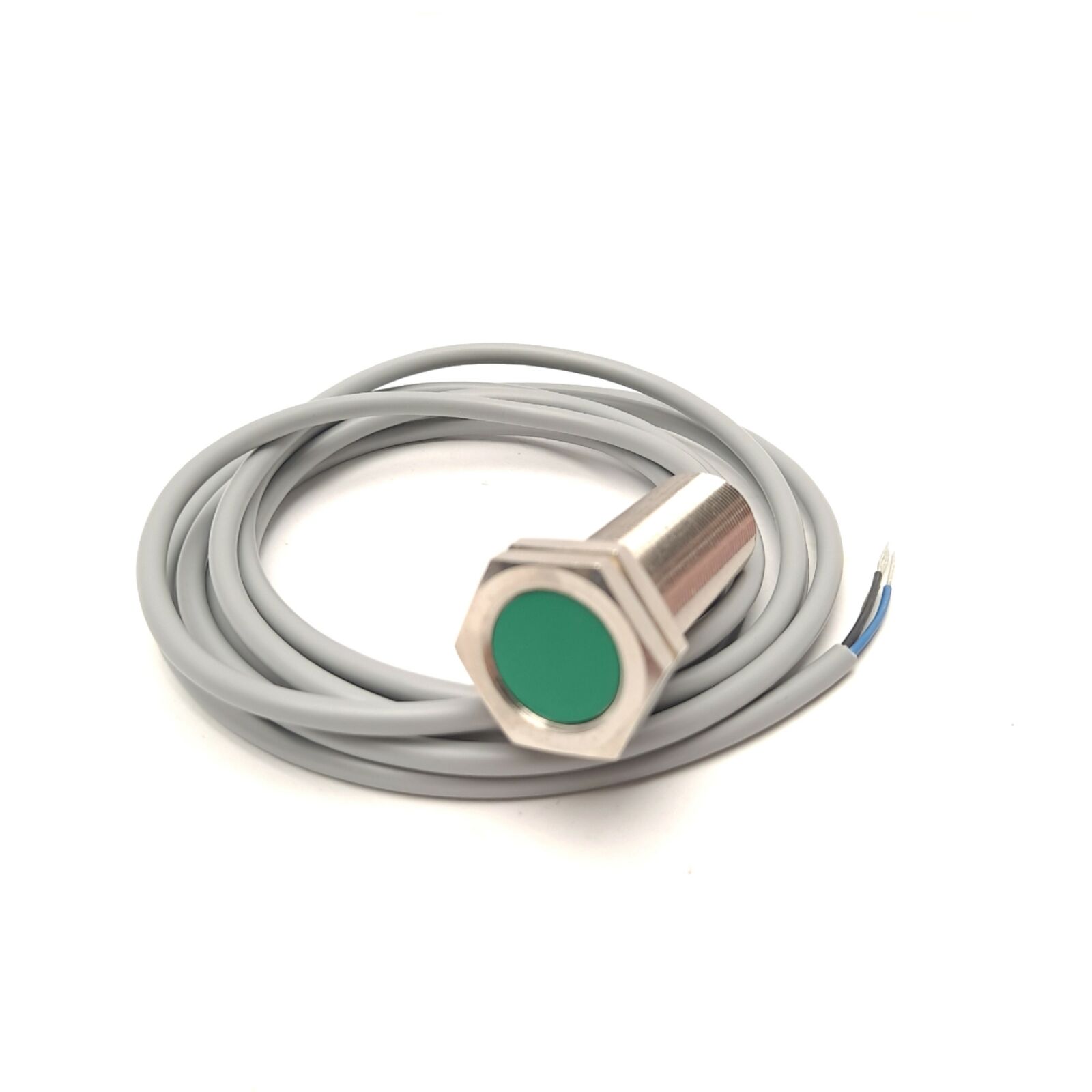
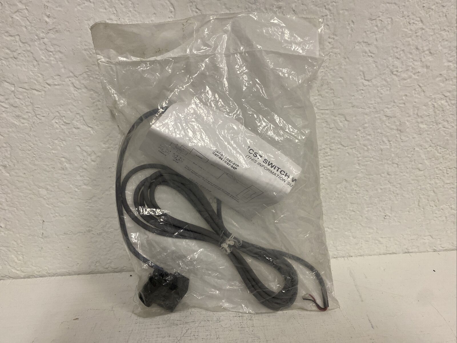
AI-TEK INSTRUMENTS Magnetic Hall Effect SENSOR DH1512-114 NIB
$ 79.2
- Description
- Size Guide
Description
AI-TEK INSTRUMENTS Magnetic Hall Effect SENSOR DH1512-114 NIB. Condition is New. Shipped with USPS First Class Package.DH SERIES
Zero Velocity - Magnetic Hall Effect Sensors - 5/8 and 3/4 Threads
AI-Tek has taken its years of experience of designing and manufacturing Hall Effect sensors for harsh applications and has developed a line of durable products for industrial, rail, military and automotive use.
The new Al-TEK DH series sensors are differential based, zero-speed, precision, single channel, speed sensors. At power-up, they calibrate themselves to the unique magnetic signature of their installed application and continue to update the calibration as the sensor is running. This unique combination of differential sensing technology and calibration make these sensors highly tolerant of installation mis-alignment, target geometry and composition, target run-out, vibration and air gap changes.
In comparison, the RH series are single-element based, zero speed, single channel speed sensors and are an excellent choice for general purpose speed sensing. Unlike the DH series that requires rotational alignment at installation, the RH requires no alignment. Air gap adjustment is precise and easy and similar to a VR type sensor.
The new DH sensor can sense each change in target movement, regardless of speed, from zero to 15 kHz frequency range, generating a steady pulse train of frequency proportional to target speed. Typically, each time a gear tooth (or any ferrous discontinuity) passes in front of the sensor the output changes state. This type of sensor is known as a "P" type because it uses N-P-N transistor logic (as opposed to "N" type, which uses P-N-P transistor logic).
Key features:
• Reverse voltage protection, to prevent damage if miswired
• Extended temperature range
• Wide range of supply voltage
• Two output options of Supply Tracking or TTL Compatible
• Rugged design meeting IEC 77 Standards (European Railroad Applications) • Require special alignment
• Improved duty cycle
• Improved fine pitch performance
• Increased air gaps
• Special circuitry provides high level of EM1 hardness
• Select versions equipped with RTD temperature measurement output
Suitable for 32 diametral pitch or coarser gear (target), the standard catalog
sensors are easily applied to your various sensing needs. If you have a unique, special requirement which cannot be met with any of the standard options, we will gladly review your specs and work with you on a special sensor design.
It is the customer's responsibility to determine whether the product is proper for customer's use and application.
AI-Tek Instruments, Cheshire, CT USA
DH SERIES
Zero Velocity - Magnetic Hall Effect Sensors - 5/8 and 3/4 Threads
Specifications
Power Supply Power Supply Voltage: 4.5 - 24 Vdc
Power Supply Current: 50 mA maximum
Outputs
Output Voltage:
Essentially square wave fanout to 10 TTL inputs
TTL Compatible: (See Figure 1) 50% ±10% duty cycle
Logic 0: +.6 Vdc maximum Logic 1: +4 to +5 Vdc @ 5mA
Supply Tracking: (See Figure 2) 50% ±10% duty cycle
Environmental
Operating Temperature:
-40°C to +125°C
Thermal Shock:
100 cycles air to air (-40° to +130°C)
1 min. ramp time with 30 min. soak
Salt Spray:
Per MIL-STD-202, method 201, test cond. B,
5% NaCl for 48 hrs. No visible corrosion
Humid ity:
92% RH@ 40°C for 90 hrs. No visible corrosion.
Dielectric Strength:
Per MIL-STD-202, method 301, 1000 Vrms (60Hz) for 5 sec. leads to case. 1.0 mA max. leakage.
Insulation Resistance:
Per MIL-STD-202, method 302, 500 Vdc for 30 sec. leads to case. 100 mega-ohm min.
Vibration:
Per MIL-STD-202, resonant frequency search, sine method 204, test cond. C&D (20g); random method 214a, test cond. A&B (7.56g) for 15 min.
Shock:
Per MIL-STD-202, method 213b (sawtooth), test cond. H&I (1 00g, 6 ms), 3 shocks, mutually perpendicular planes
Materials
Housing:
300 series stainless steel Connector: MIL Style
Mates with MS3106A10SL-3S Leads: (Available on special request) AWG #24 Teflon, 200°C
Cable:
AWG #20 Irradiated cross-linked polyolefin, 125°C
Alignment:
Rotational alignment of sensing face is required for optimum output signal. Align flats with direction of rotation.
Logic 0:
Logic 1:
+.6 Vdc maximum
Vo =
Vs x RL RL + 2.2k
Output Impedance:
Output Current: 20 mA sink maximum
Output Current - Short Circuit:
5 mA maximum with 10V power supply Reverse Battery Voltage: -30 Vdc Defined Power on State - High Single Tooth/Valley Compatible
Mechanical Target Frequency:
0 to 15 kHz
Target Air Gap:
.005 to .025 with a 32 diametral pitch gear .005 to .055 with a 24 diametral pitch gear .005 to .100 with a 20 diametral pitch gear .005 to .120 with a 12 diametral pitch gear .005 to .175 with an 8 diametral pitch gear Automatic Calibration:
Power up +3 edges Running Update
